Verification of masonry structures, from the whole building to a single wall.
Two modules compliant with NTC 2018 and the Circolare 2019. The Buildings module covers the full global calculation flow of a building; the Openings module verifies cutting or modifying openings in a wall as a local intervention.
Buildings module
Pin the site, choose the materials, model the structure. The Buildings module covers the full calculation flow of a masonry building: site-resolved actions, equivalent frame, gravity loads, modal analysis, global pushover, out-of-plane local mechanisms.
Site-driven actions
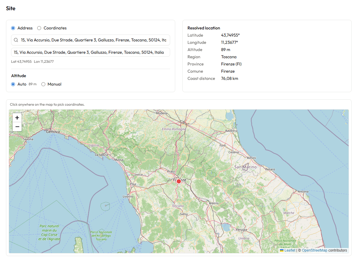
Drop a pin in Italy and SMART masonry resolves the seismic, wind and snow action parameters automatically, cutting the strictly-manual work down to almost nothing. Province and region, height above sea level, distance from coast, seismic hazard and zone — all derived automatically.
Resolved automatically from one pin
- Province, region and comune (ISTAT polygons)
- Elevation above sea level
- Distance from coast (with minor-island detection)
- Wind zone and exposure category
- Snow zone and altitude-corrected qsk
- Seismic hazard (GNDT grid)
Masonry characterisation
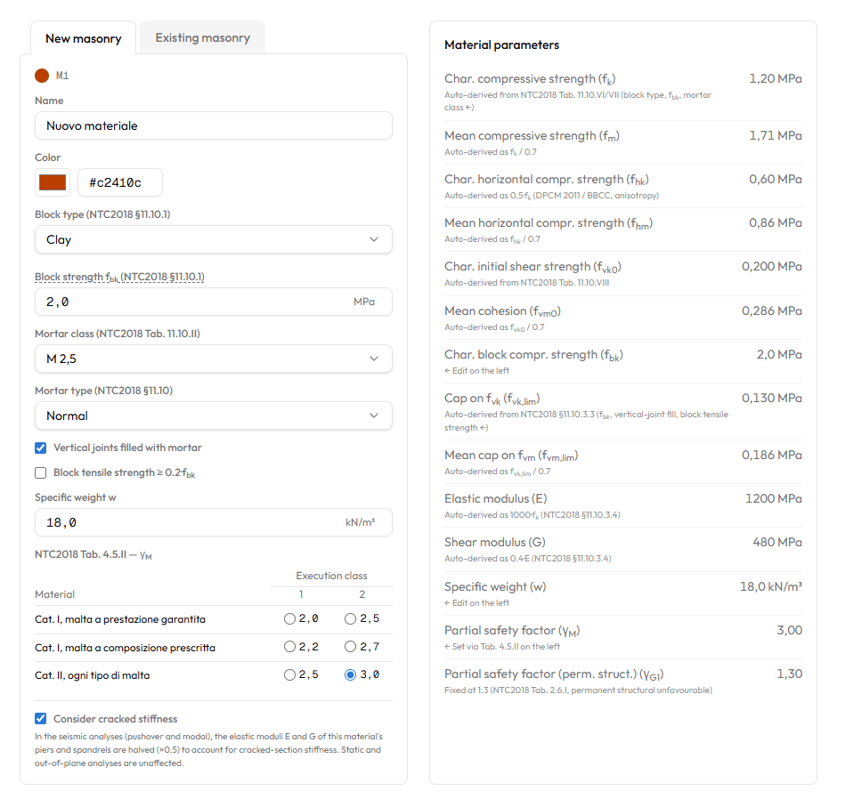
Masonry constitutive parameters come from two distinct chains: existing or new masonry.
Existing masonry
Pick a typology (e.g. roughly-shaped stone, solid brick with lime mortar) and a knowledge level (LC1 / LC2 / LC3). Tab. C8.5.I seeds the six mechanical properties; Tab. C8.5.II layers the intervention coefficients on top — buona malta, regular brick courses (ricorsi), systematic transverse connections, consolidamento (iniezioni, intonaco armato, ristilatura armata), artificial diatons.
New masonry
Pick the block type, mortar class M and unit characteristic strength fbk. The engine interpolates Tab. 11.10.VI / VII for fk and Tab. 11.10.VIII for fvk,0; the moduli follow NTC §11.10.3.4 (E = 1000·fk, G = 0.4·E).
Macro-element model
Walls are treated as an assembly of piers (the masonry between openings) and spandrels (the masonry above and below openings), connected by rigid nodes — the equivalent-frame approach explicitly endorsed by NTC 2018.
Piers and spandrels are modelled as Timoshenko 2-node beams with rigid end-offsets. They develop plastic hinges in compression-bending and a plastic shear hinge in shear, both with displacement-controlled damage.
3D consistency is obtained by connecting walls through deformable floors, modelled as orthotropic membrane elements.
Heterogeneous degrees of freedom
Full 3D node carrying mass. Connects non-collinear walls to each other and walls to floors.
In-plane to a wall alignment only. Guarantees each wall contributes stiffness and strength in its own plane. Vertical loads land here.
Horizontal translation only. Belongs to floors alone (balconies, openings in slabs).
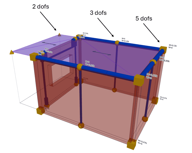
Wall self-weight is split half to the bottom-level node and half to the top-level node of the panel it belongs to, so the gravity-load path mirrors the geometry.
Non-seismic load analysis
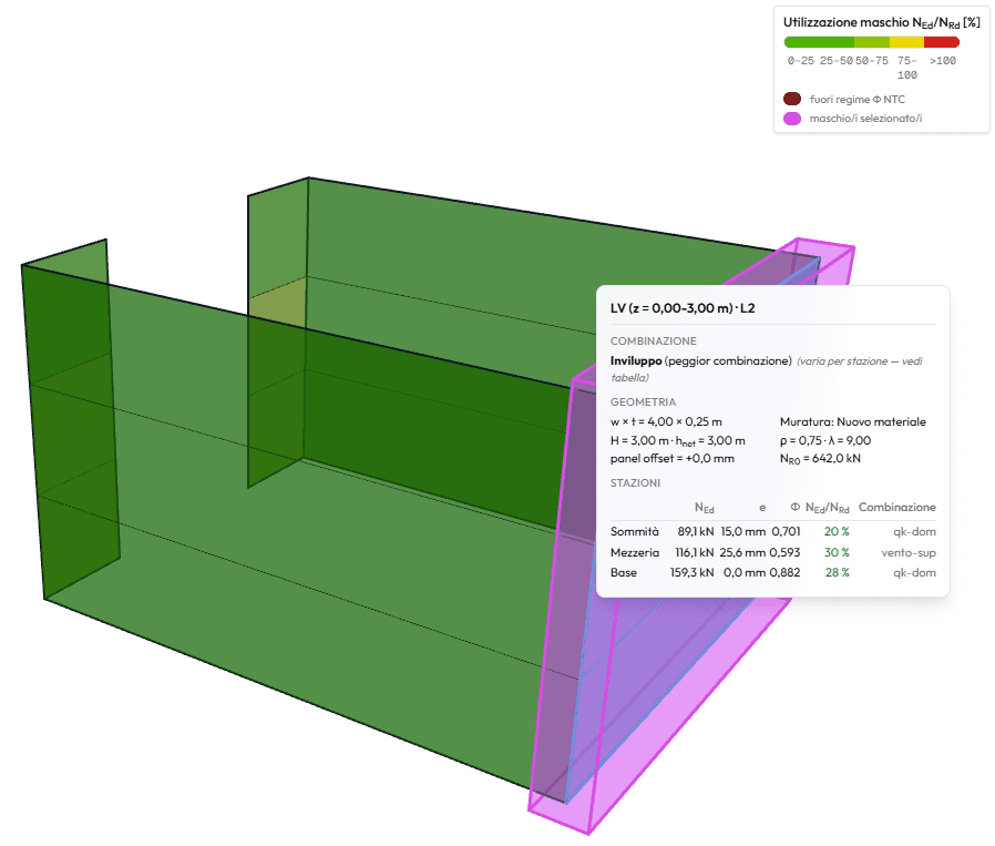
Gravity-load analysis runs as a load-controlled static. It provides the axial-load demand on each wall and is explicitly designed to avoid unphysical vertical-load transfers between non-collinear walls.
Compression and out-of-plane stability are then checked strictly against NTC 2018 §4.5, including the effective-height factor ρ and the Φ stability correction.
Modal analysis
Modal analysis runs on the same 3D macro-element model by solving the dynamic eigenproblem K · φ = ω² · M · φ. Periods, mode shapes, participation coefficients and participating mass ratios are evaluated from the solution of the problem via the Lanczos shift-invert algorithm.
Seismic nonlinear static analysis
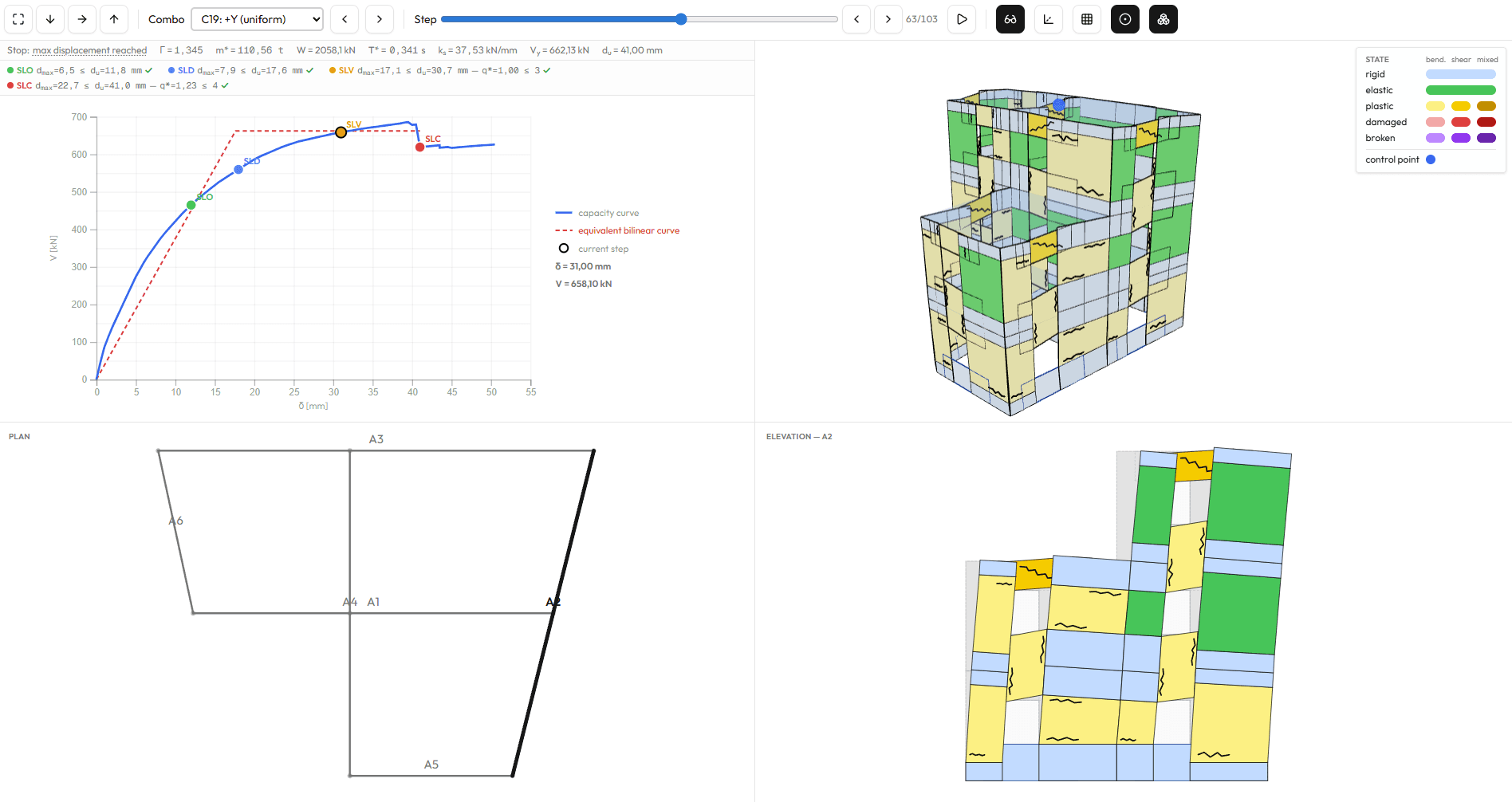
The analysis runs in two steps. First, vertical loads in the seismic combination are applied with the same per-wall approach used in the non-seismic analysis, in a static load-control pass. Then 24 seismic combinations are generated and each runs a nonlinear pushover with indirect displacement control. The controlled displacement defaults to the top-storey mass centre; however, the user can select the mass centre of a different level (for example, when small rooftop towers are present).
24 combinations, run in parallel
- 2 load distributions: proportional to mass, first-mode shape
- 4 directions: ±X, ±Y
- 3 accidental eccentricities: none, +5%, −5%
During each analysis, plasticisation is monitored together with partial or total damage on piers and spandrels. Damaged elements unload and the residual action redistributes to the neighbours. Piers are checked in compression-bending (rocking and toe-crushing) and in shear under the user-selected criterion (Turnšek–Čačovič or Mohr–Coulomb); spandrels follow analogous criteria from Circolare 2019.
On each base shear vs. controlled-displacement curve the capacity limit states are identified. The structure is then reduced to an equivalent elastic-plastic SDOF system: the displacement demand for each limit state is read from there, and the verification index ζE is produced.
Out-of-plane local mechanisms
In-plane pushover is only half of the seismic story: a wall can overturn out of its own plane before the global structure reaches its capacity.
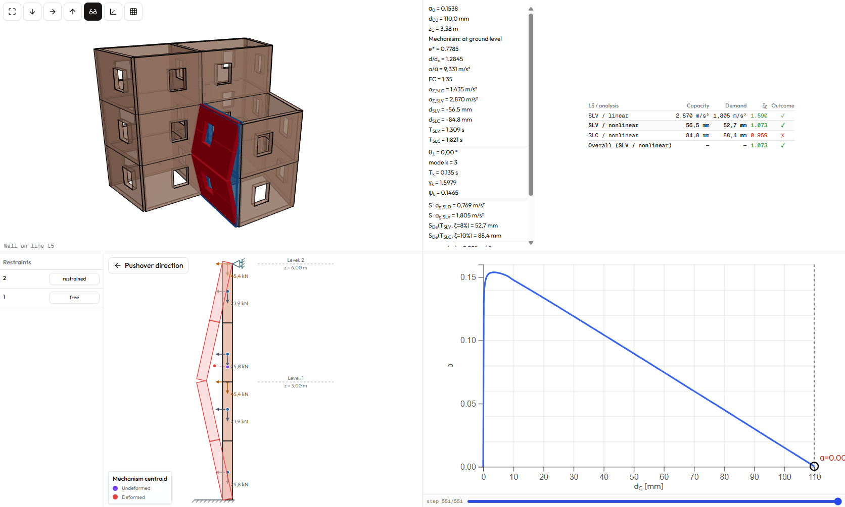
SMART masonry follows a unique approach: the wall's transverse section is modelled as rigid blocks interacting through nonlinear elastic-plastic interfaces (no-tension, no-sliding, finite elasticity and optional finite compressive strength). Rather than postulating a predefined mechanism (e.g. simple overturning), an out-of-plane pushover is run on the block assembly and the weakest mechanism activates automatically.
Geometric nonlinearities are handled with a co-rotational formulation, so the full overturning of a block can be traced correctly, as required by the nonlinear kinematic analysis of Circolare 2019.
Openings module (local interventions)
The Openings module analyses a single masonry wall in which new openings are cut or existing ones are modified, comparing its response before and after the intervention per NTC 2018 §8.4.1, Circolare 2019 §C8.4.1 and the Regione Toscana interpretive guidelines.
Existing state and design state
Cutting new openings in a wall, with suitable strengthening, counts as a local intervention: the verification may refer to that wall alone, provided the intervention does not significantly change its stiffness nor reduce its strength and displacement capacity.
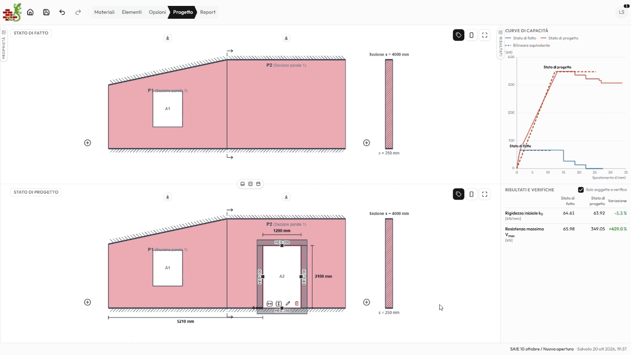
The wall is drawn as a sequence of panels, each with its own wall section, loads and static scheme (cantilever or shear-type). The two configurations, existing state and design state, sit side by side in the same view: every change to the openings updates both capacity curves and the variation table live.
Configurable checks
- Stiffness: initial or secant, with the change within a limit (typically ±15%)
- Strength: peak or equivalent-bilinear, not reduced or within a limit
- Displacement: at failure of the first pier, of all piers, or the bilinear ultimate
- Energy: area under the capacity curve, reported or checked as not reduced
Pier stiffness, strength and displacement
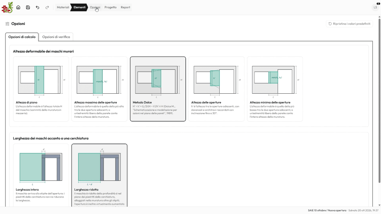
In each configuration the wall is automatically split into masonry piers, bounded by the openings and by the panel ends; overlapping openings are merged. The deformable height of a pier is chosen among five criteria.
Deformable height
- Storey height
- Opening height, with 30° spread
- Maximum height of the adjacent openings
- Minimum height of the adjacent openings
- Dolce method (1989)
Lateral stiffness combines flexural and shear deformability in series, with a cantilever or shear-type scheme. Strength is the lower of combined compression and bending and shear (Turnšek–Čačović or Mohr–Coulomb for existing masonry, sliding for new masonry), with the axial force taken in the seismic combination over the tributary width of the pier.
Each pier behaves elastic–perfectly plastic, with the ultimate displacement expressed as a drift limit depending on the governing failure mode. Infilled openings stay voids for the split, but each infill is a pier of its own.
Steel frames, lintels and infills
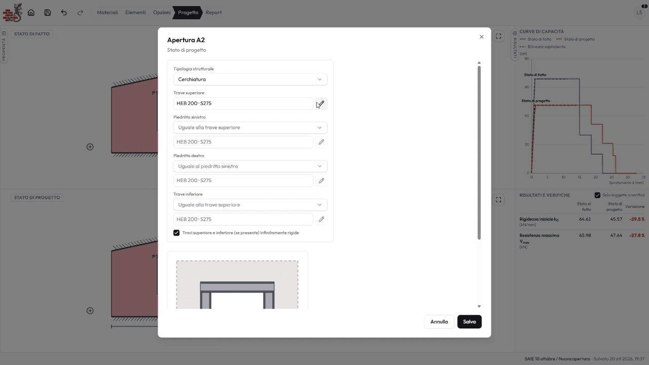
Each opening owns its structure: free, with a lintel, with a steel frame, or infilled. Frame members are built from a library of IPE, HEA, HEB, HEM and UPN profiles, also side by side, or from custom I or C sections.
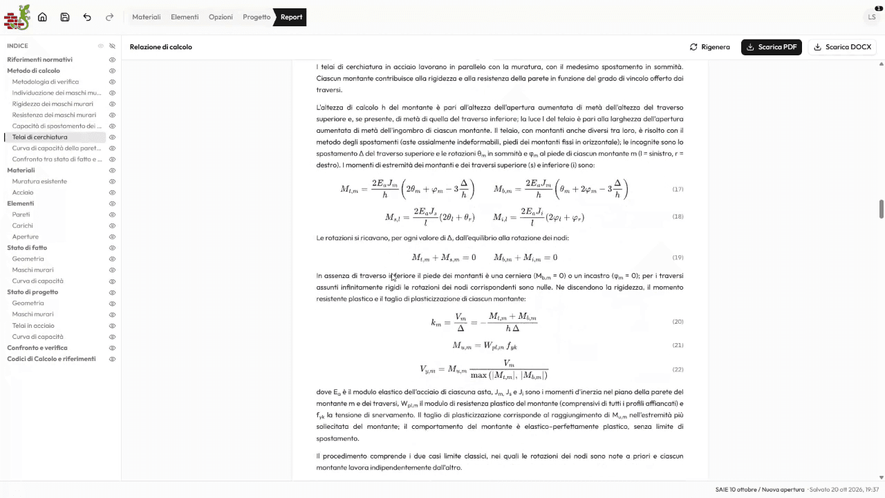
The frame works in parallel with the masonry, with the same top displacement, and is solved with the displacement method: frame piers that may differ from each other, deformable or infinitely rigid beams, an optional bottom beam with pinned or fixed feet. The classic cantilever and shear-type schemes are special cases.
Optionally, the width of the adjacent piers is reduced by the frame piers housed in the masonry beyond the jambs, and the opening is enlarged in height by the beams.
Capacity curve, verification and report
The wall capacity curve sums, for every top displacement, the contributions of all masonry piers and of all steel-frame piers. It is paired with an elastic–perfectly plastic equivalent bilinear: secant stiffness at 0.7·Vmax and strength from equal areas up to the ultimate displacement.
The existing-vs-design comparison reports the percentage changes in stiffness, strength and displacement and establishes whether the intervention qualifies as local; if not, it flags that the intervention must be assessed within the global behaviour of the building.
The calculation report gathers method, formulas, materials, geometry and the curves of both states, and downloads as PDF and DOCX.